

Software Design Review Outline
EN
Introduction to UML Class Diagrams
UML (Unified Modeling Language) is a standard graphical language used to model the structure and behavior of software systems. UML is not a programming language but a design language that allows software engineers to represent different aspects of the system graphically. UML includes various diagrams, with class diagrams being the most commonly used.
UML diagrams are divided into three main categories:
- Use case diagrams
- Static structure diagrams: class diagrams, object diagrams, package diagrams, component diagrams, deployment diagrams
- Dynamic behavior diagrams: interaction diagrams (sequence diagrams and collaboration diagrams), state diagrams, activity diagrams
Basic Elements of Class Diagrams
- Class:
- A class is the primary element in a UML class diagram, represented by a rectangle typically divided into three parts:
- The first part is the class name.
- The second part contains the class attributes or member variables. (Static member variables are prefixed with
_). - The third part contains the class operations or methods.
- Class names typically start with uppercase letters. The visibility of attributes and methods can be indicated using symbols (e.g.,
+for public,-for private,#for protected,~for default (package scope)). - Italic: Abstract classes (note: they can also be indicated with double angle brackets, e.g., <
>). - Before the colon is the method/variable name (distinguished by the presence or absence of parentheses), after the colon is the return parameter/variable type (distinguished by the presence or absence of parentheses). If there is no colon, it means the method returns void (sometimes
:voidis used to indicate void returns).
- A class is the primary element in a UML class diagram, represented by a rectangle typically divided into three parts:
- Relationship:
- Relationships describe the connections between classes. Common relationships include:
- Association: A regular connection between two classes, indicating that one object is associated with another.
- Dependency: A change in one class might affect another class.
- Aggregation: A special association representing a “whole-part” relationship, but the part can exist independently of the whole.
- Composition: A stronger “whole-part” relationship than aggregation, where the part cannot exist independently of the whole.
- Generalization: An inheritance relationship representing a more general class (parent) and a more specific class (child).
- Realization: The relationship between an interface and the class that implements it.
- Relationships describe the connections between classes. Common relationships include:
- Multiplicity:
- Indicates the number of instances in a relationship. For example, a teacher can teach multiple students, while a student typically belongs to one class, and these relationships can be represented by multiplicity.
- Interface:
- An interface defines a set of operations but does not implement them. Classes can implement one or more interfaces.
Steps to Create Class Diagrams
- Identify Classes:
- Usually correspond to entities, concepts, or objects in the system.
- Define Attributes and Methods:
- Determine each class’s responsibilities and functions.
- Establish Relationships:
- Analyze how classes interact and represent these interactions with appropriate relationship types.
- Determine Multiplicity:
- Define the number of objects in each relationship.
- Check and Optimize:
- Verify that the class diagram accurately reflects the system’s requirements and make necessary optimizations to the design.
Uses of Class Diagrams
- Design the static structure of the system.
- Help understand the relationships and interactions between objects in the system.
- Serve as blueprints for system development and guide programming.
- Provide system documentation to help new team members understand the system structure.
Below is a detailed discussion of the six types of class relationships.
Relationships Between Classes
Dependency
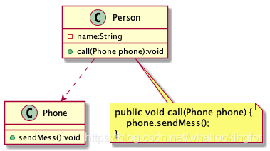
Dependency, in code, refers to a situation where a method of one class uses local variables, method parameters, or static method calls to access some methods of another class (the dependent class) to complete certain tasks. Simply put, Class A uses another Class B, so A depends on B, forming a dependency relationship. However, this usage relationship is incidental, temporary, and very weak, but changes in Class B will affect Class A, indicating a usage relationship.
- Code: method parameters, local variables
- UML: a dashed line with an arrow pointing from the using class to the dependent class
Association
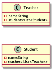
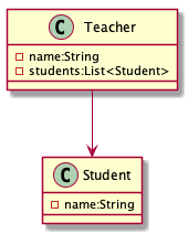
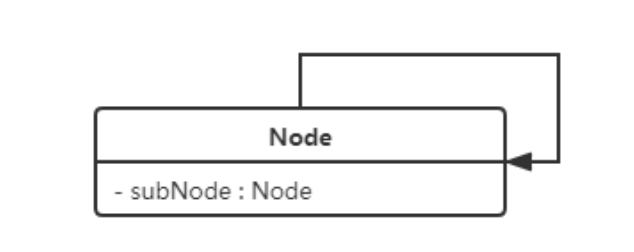
Association is used to represent a connection between objects of one class and objects of another class, enabling one class to know the attributes and behaviors of another class. Associations can be unidirectional, bidirectional, or self-associative.
For example: A teacher and a student. A teacher knows the information of students in the class, but students do not know the teacher’s information, representing a unidirectional association. If both the teacher and the student know each other’s information, it represents a bidirectional association. If a teacher knows information about other teachers, it represents a self-association.
Code: usually achieved by making an object of one class a member variable of another class.
UML: bidirectional associations can be represented with two arrows or without arrows. Unidirectional relationships use one arrow pointing from the using class to the associated class.
Bidirectional Association
Unidirectional Association
Self Association
Aggregation
Aggregation is a strong association that represents a whole-part relationship, indicated by
has-a. Aggregation is achieved through member objects, where the member object is part of the whole but can exist independently.
For example: The relationship between a school and a teacher. The school includes teachers, but if the school closes, the teachers still exist.
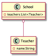
- UML: Aggregation is usually represented by a solid line with a hollow diamond pointing to the whole.
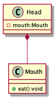
Composition
Composition is a stronger form of association than aggregation, also representing a whole-part relationship. The whole object controls the lifecycle of the part object. If the whole object ceases to exist, the part object will also cease to exist. Part objects cannot exist independently of the whole object.
For example: The relationship between a head and a mouth. Without the head, the mouth does not exist.
- UML: Composition is represented by a solid line with a solid diamond pointing to the whole.
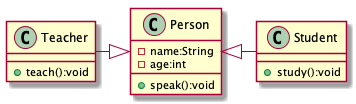
Generalization
Generalization represents an inheritance relationship, the highest degree of coupling between objects, indicated by
is-a.
For example: Student and teacher classes are subclasses of the person class.
- UML: Generalization is represented by a solid line with a hollow triangular arrow pointing from the subclass to the parent class.
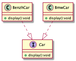
Realization
Realization represents the relationship between an interface and the class that implements it.
Object-Oriented Design Principles
Open-Closed Principle
(Open-Closed Principle)
- Definition: Software entities (such as classes, modules, functions, etc.) should be open for extension but closed for modification. This means software should be designed to allow the addition of new functionality without changing existing code.
- Implementation: By using interfaces and abstract classes, functionality can be extended by adding new derived classes without directly modifying existing code.
Liskov Substitution Principle
- Definition: In software, if one class is a subclass of another, then they should be interchangeable without affecting the execution of the program. This means subclasses should extend the functionality of parent classes without altering their behavior.
- Implementation: Ensure that subclasses only extend and do not modify the behavior of parent classes. Objects of the subclass should be able to replace all instances of the parent class without
causing errors.
Dependency Inversion Principle
- Definition: High-level modules (complex business logic) should not depend on low-level modules (specific data operations). Both should depend on abstractions (e.g., interfaces). Moreover, abstractions should not depend on details; details should depend on abstractions.
- Implementation: Use abstract classes and interfaces to construct relationships between high-level and low-level modules, ensuring their decoupling.
Composition Over Inheritance Principle
- Definition: Favor object composition over class inheritance to achieve code reuse.
- Implementation: When designing new systems, consider implementing functionality as a set of independent components that can be used by other objects, rather than adding functionality through extending existing classes.
Single Responsibility Principle
- Definition: A class should have only one reason to change, meaning it should have only one responsibility.
- Implementation: Ensure that each class focuses on a single function or responsibility. If a class has multiple functions, consider splitting it into smaller, more focused classes.
Law of Demeter
- Definition: A class should have limited knowledge of other classes, and should only communicate with its immediate friends, not with strangers.
- Implementation: Design classes to limit their interactions with other classes. Avoid direct dependencies on the specific implementations of other classes, instead using interfaces or abstract classes for interaction.
Interface Segregation Principle
- Definition: Clients should not be forced to depend on interfaces they do not use. A class’s dependency on another class should be based on the smallest possible interface.
- Implementation: Design fine-grained, specific interfaces rather than a large, all-encompassing one. This ensures that implementing classes only need to provide methods they actually use.
Types of Design Patterns
Overall, design patterns are divided into three categories and 23 types:
Creational (5 types): Factory Pattern, Abstract Factory Pattern, Singleton Pattern, Prototype Pattern, Builder Pattern
Structural (7 types): Adapter Pattern, Decorator Pattern, Proxy Pattern, Facade Pattern, Bridge Pattern, Composite Pattern, Flyweight Pattern
Behavioral (11 types): Template Method Pattern, Strategy Pattern, Observer Pattern, Mediator Pattern, State Pattern, Chain of Responsibility Pattern, Command Pattern, Iterator Pattern, Visitor Pattern, Interpreter Pattern, Memento Pattern
CN
UML类图简介
UML(统一建模语言)是一种标准的图形语言,用于建模软件系统的结构和行为。UML不是一种编程语言,而是一种设计语言,它允许软件工程师以图形化的方式表示系统的不同方面。UML有多种不同的图,其中类图(Class Diagram)是最常用的一种。
UML图分为三大类:
- 用例图
- 静态结构图:类图,对象图,包图,组件图,部署图
- 动态行为图:交互图(时序图与协作图),状态图,活动图
类图的基础元素
- 类(Class):
- 类是UML类图中的主要元素,它用矩形框表示,通常分为三个部分:
- 第一部分是类名。
- 第二部分是类的属性或成员变量。(静态成员变量前要加
_) - 第三部分是类的操作或方法。
- 类名通常用大写字母开始,属性和方法的可见性可以用符号表示(如
+代表公共,-代表私有,#代表受保护,~: default ( package 维度 ))。 - 斜体: 抽象 ==(注意也可以用两个尖括号包裹来表示抽象,比如 —— <<我是抽象类or接口>>)==
- 冒号前是方法名/变量名(根据有无括号区分),冒号后是返回参数/变量类型(根据有无括号区分),如果没有冒号的话表示方法返回空(也有人通过:void表示返空)
- 类是UML类图中的主要元素,它用矩形框表示,通常分为三个部分:
- 关系(Relationship):
- 关系描述类与类之间的连接。常见的关系包括:
- 关联(Association):两个类之间的普通连接,表示一个对象与另一个对象有关联。
- 依赖(Dependency):一个类的改变可能影响到另一个类。
- 聚合(Aggregation):一种特殊的关联,表示“整体”和“部分”的关系,但部分可以脱离整体存在。
- 组合(Composition):比聚合更强的“整体-部分”关系,部分不能脱离整体存在。
- 泛化(Generalization):即继承关系,表示一个更一般的类(父类)和一个更特殊的类(子类)之间的关系。
- 实现(Realization):接口和实现该接口的类之间的关系。
- 关系描述类与类之间的连接。常见的关系包括:
- 多重性(Multiplicity):
- 表示对象间关联的数量。例如,一个教师可以教多个学生,而一个学生通常只属于一个班级,这些关系的数量就可以用多重性来表示。
- 接口(Interface):
- 接口定义了一组操作,但不实现这些操作。类可以实现(realize)一个或多个接口。
创建类图的步骤
- 识别类:
- 通常对应于系统中的实体、概念或对象。
- 定义属性和方法:
- 确定每个类的责任和功能。
- 建立关系:
- 分析类之间如何相互作用,并使用适当的关系类型来表示这些关系。
- 确定多重性:
- 定义每种关系中的对象数量。
- 检查和优化:
- 验证类图是否准确地反映了系统的需求,并对设计进行必要的优化。
类图的用途
- 设计系统的静态结构。
- 帮助理解系统中对象的关系和交互。
- 作为系统开发的蓝图,指导编程。
- 提供系统文档,帮助新团队成员理解系统结构。
下面对类的六种关系进行详细讨论
类间关系
依赖(Dependency)
依赖(dependency),在代码中,某个类的方法通过局部变量,方法参数或者对静态方法的调用来访问另一个类(被依赖类)中的某些方法来完成一些任务.
通俗的讲,一个类A使用到了另一个类B,那A就依赖于B,即构成了依赖关系,但是这种使用关系是具有偶然性的、临时性、非常弱的,但是B类的变化会影响到A,是一种使用关系
- 代码:方法的参数,局部变量
- UML:一条虚线,箭头从使用类指向被依赖的类
关联(Association)
关联(association)关系,用于表示一类对象与另一类对象之间的联系,使一个类知道另一个类的属性和行为.关联关系有单向关联,双向关联,自关联
举例:比如老师和学生,老师知道班里的学生信息,学生不知道老师的信息,老师和学生就是一种单向的关联关系.老师知道学生信息,学生知道老师信息,两者之间就是双向关联关系.老师知道同行老师的信息,老师和老师就是自关联关系.
代码:通常是将一个类的对象作为另一个类的成员变量来实现.
UML:双向关联可以用带两个箭头或者没有箭头的实现来表示.单向关系用带一个箭头的实现从实用类指向被关联类
双向关联
单向关联
自关联
聚合(Aggregation)
聚合(aggregation)关系是关联关系的一种,是强关联关系,是整合和部分的关系,是
has-a的关系
聚合关系也是通过成员对象来实现,其中成员对象是整体对象的一部分,但是成员对象可以脱离整体对象单独存在
- 举例:学校与老师关系,学校中包含老师,如果学校停办了,老师依然存在.
- UML:聚合关系通常用带空心的菱形实线来表示,菱形指向整体.
组合(Composition)
组合(composition)关系也是关联关系的一种,也是表示整体和部分的关系,整体对象控制部分对象的生命周期,一旦整理对象不存在,部分对象也将不存在.部分对象不能脱离整理对象单独存在.
- 举例:头和嘴的关系,没了头,嘴也就不存在了.
- UML:组合关系用带实心的菱形实线来表示,菱形指向整体.
泛化(Generalization)
泛化(generalization)关系是对象之间耦合度最大的关系,是父类与子类的继承关系,是
is-a的关系
- 举例:学生类和老师类都是person类的子类.
- UML:泛化关系用带空心三角箭头的实线来表示,箭头从子类指向父类
实现(Realization)
实现(realization)关系是接口与实现类之间的关系.
面向对象的设计原则
开闭原则
(Open-Closed Principle)
- 定义:软件实体(如类、模块、函数等)应该对扩展开放,对修改关闭。这意味着软件应该设计成在不改变现有代码的情况下,可以增加新功能。
- 实施方法:通过使用接口和抽象类,可以在不直接修改现有代码的情况下,通过添加新的派生类来扩展功能。
里氏代换原则
- 定义:在软件中,如果一个类是另一个类的子类,则它们应该可以互换而不影响程序的执行。这意味着子类在扩展父类的功能时,不应改变原有类的行为。
- 实施方法:确保子类只扩展而不改变父类的行为。子类的对象应该能够替换所有使用父类的地方而不产生错误。
依赖倒置原则
- 定义:高层模块(如复杂的业务逻辑)不应依赖于低层模块(如具体的数据操作),两者都应依赖于抽象(如接口)。同时,抽象不应依赖于细节,细节应依赖于抽象。
- 实施方法:使用抽象类和接口来构建系统的高层和低层模块之间的关系,确保它们之间的解耦
合成-聚合复用原则
- 定义:应优先使用对象的组合或聚合来实现代码的重用,而不是通过继承。
- 实施方法:在设计新系统时,考虑将功能作为一组可被其他对象使用的独立组件,而不是通过扩展现有类来添加功能。
单一职责原则
- 定义:一个类应该只有一个引起变化的原因。换句话说,一个类应该只有一个职责。
- 实施方法:在设计类时,确保每个类只关注单一的功能或责任。如果一个类有多种功能,考虑将其拆分成多个更小的类。
迪米特法则
- 定义:一个对象应该对其他对象保持最小的了解。实质上,一个对象应该只与直接的朋友类通信,不与陌生类通信。
- 实施方法:在设计类时,限制其与其他类的交互。如果可能,避免直接依赖于其他类的具体实现,而是通过接口或抽象类交互。
接口隔离原则
- 定义:不应该强迫客户依赖于它们不使用的接口。一个类对另一个类的依赖应该建立在最小的接口上。
- 实施方法:设计细小的、具体的接口,而不是一个大而全的接口。这样可以确保实现类只需实现它们真正需要的方法。
设计模式的类型
总体来说,设计模式分为三类23种:
- 创建型(5种):工厂模式、抽象工厂模式、单例模式、原型模式、构建者模式
- 结构型(7种):适配器模式、装饰模式、代理模式、外观模式、桥接模式、组合模式、享元模式
- 行为型(11种):模板方法模式、策略模式、观察者模式、中介者模式、状态模式、责任链模式、命令模式、迭代器模式、访问者模式、解释器模式、备忘录模式